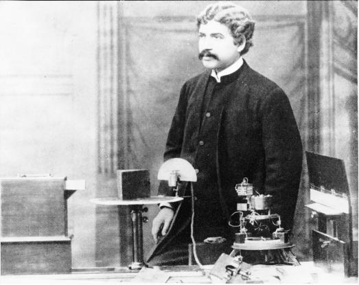
Figure 1. J.C. Bose at the Royal Institution, London, 1897. [13]
THE WORK OF JAGADIS CHANDRA BOSE:
100 YEARS OF MM-WAVE RESEARCH
National Radio Astronomy Observatory(1)
949 N. Cherry Avenue
Tucson, Arizona 85721
E-mail:
demerson@nrao.edu
(1)The National Radio Astronomy Observatory is a facility of the National Science Foundation, operated under cooperative agreement by Associated Universities, Inc.
ABSTRACT
Just one hundred years ago, J.C. Bose described to the Royal Institution in London his research
carried out in Calcutta at millimeter wavelengths. He used waveguides, horn antennas, dielectric
lenses, various polarizers and even semiconductors at frequencies as high as 60 GHz; much of his
original equipment is still in existence, now at the Bose Institute in Calcutta. Some concepts from
his original 1897 papers have been incorporated into a new 1.3-mm multi-beam receiver now in
use on the NRAO 12 Meter Telescope.
INTRODUCTION
James Clerk Maxwell's equations predicting the existence of electromagnetic radiation
propagating at the speed of light were made public in 1865; in 1888 Hertz had demonstrated
generation of electromagnetic waves, and that their properties were similar to those of light [1].
Before the start of the twentieth century, many of the concepts now familiar in microwaves had
been developed [2,3]: the list includes the cylindrical parabolic reflector, dielectric lens,
microwave absorbers, the cavity radiator, the radiating iris and the pyramidal electromagnetic
horn. Round, square and rectangular waveguides were used, with experimental development
anticipating by several years Rayleigh's 1896 theoretical solution [4] for waveguide modes. Many
microwave components in use were quasi-optical - a term first introduced by Oliver Lodge [5].
Righi in 1897 published a treatise on microwave optics [6].
Hertz had used a wavelength of 66 cm; other post-Hertzian pre-1900 experimenters used
wavelengths well into the short cm-wave region, with Bose in Calcutta [7,8] and Lebedew in
Moscow [9] independently performing experiments at wavelengths as short as 5 and 6 mm.
THE RESEARCHES OF J.C. BOSE
Jagadis Chandra Bose [10,11,12] was born in India in 1858. He received his education first in
India, until in 1880 he went to England to study medicine at the University of London. Within a
year he moved to Cambridge to take up a scholarship to study Natural Science at Christ's College
Cambridge. One of his lecturers at Cambridge was Professor Rayleigh, who clearly had a
profound influence on his later work. In 1884 Bose was awarded a B.A. from Cambridge, but
also a B.Sc. from London University. Bose then returned to India, taking up a post initially as
officiating professor of physics at the Presidency College in Calcutta. Following the example of
Lord Rayleigh, Jagadis Bose made extensive use of scientific demonstrations in class; he is
reported as being extraordinarily popular and effective as a teacher. Many of his students at the
Presidency College were destined to become famous in their own right - for example S.N. Bose,
later to become well known for the Bose-Einstein statistics.
A book by Sir Oliver Lodge, "Heinrich Hertz and His Successors," impressed Bose. In 1894, J.C.
Bose converted a small enclosure adjoining a bathroom in the Presidency College into a
laboratory. He carried out experiments involving refraction, diffraction and polarization. To
receive the radiation, he used a variety of different junctions connected to a highly sensitive
galvanometer. He plotted in detail the voltage-current characteristics of his junctions, noting their
non-linear characteristics. He developed the use of galena crystals for making receivers, both for
short wavelength radio waves and for white and ultraviolet light. Patent rights for their use in
detecting electromagnetic radiation were granted to him in 1904. In 1954 Pearson and Brattain
[14] gave priority to Bose for the use of a semi-conducting crystal as a detector of radio waves.
Sir Neville Mott, Nobel Laureate in 1977 for his own contributions to solid-state electronics,
remarked [12] that "J.C. Bose was at least 60 years ahead of his time" and "In fact, he had
anticipated the existence of P-type and N-type semiconductors."
In 1895 Bose gave his first public demonstration of electromagnetic waves, using them to ring a bell remotely and to explode some gunpowder. In 1896 the Daily Chronicle of England reported: "The inventor (J.C. Bose) has transmitted signals to a distance of nearly a mile and herein lies the first and obvious and exceedingly valuable application of this new theoretical marvel." Popov in Russia was doing similar experiments, but had written in December 1895 that he was still entertaining the hope of remote signalling with radio waves. The first successful wireless signalling experiment by Marconi on Salisbury Plain in England was not until May 1897. The 1895 public demonstration by Bose in Calcutta predates all these experiments. Invited by Lord Rayleigh, in 1897 Bose reported on his microwave (millimeter-wave) experiments to the Royal Institution and other societies in England [8]. The wavelengths he used ranged from 2.5 cm to 5 mm. In his presentation to the Royal Institution in January 1897 Bose speculated [see p.88 of ref.8] on the existence of electromagnetic radiation from the sun, suggesting that either the solar or the terrestrial atmosphere might be responsible for the lack of success so far in detecting such radiation - solar emission was not detected until 1942, and the 1.2 cm atmospheric water vapor absorption line was discovered during experimental radar work in 1944. Figure 1 shows J.C. Bose at the Royal Institution in London in January 1897; Figure 2 shows a matching diagram, with a brief description of the apparatus.
Figure 1. J.C. Bose at the Royal Institution, London, 1897. [13]
By about the end of the 19th century, the interests of Bose turned away from electromagnetic waves to response phenomena in plants; this included studies of the effects of electromagnetic radiation on plants, a topical field today. He retired from the Presidency College in 1915, but was appointed Professor Emeritus. Two years later the Bose Institute was founded. Bose was elected a Fellow of the Royal Society in 1920. He died in 1937, a week before his 80th birthday; his ashes are in a shrine at the Bose Institute in Calcutta.
Figure 2. Bose's apparatus demonstrated to the Royal Institution in London in 1897 [8]. Note the waveguide radiator on the transmitter at left, and that the "collecting funnel" (F) is in fact a pyramidal electromagnetic horn antenna, first used by Bose.
BOSE'S APPARATUS
Bose's experiments were carried out at the Presidency College in Calcutta, although for demonstrations he developed a compact portable version of the equipment, including transmitter, receiver and various microwave components. Some of his original equipment still exists, now at the Bose Institute in Calcutta. In 1985 the author was permitted by the Bose Institute to examine and photograph some of this original apparatus.
3(a)
3(b)
Figure 3 Bose's diagrams of his radiators. (a) shows the radiator used to generated 5-mm
radiation, while (b) shows the arrangement with a lens
L at the exit of the waveguide [2].
In some designs the mounting stems for the outer spheres could be inclined to adjust the
dimension of the spark gaps.
Figure 3 (a) shows Bose's diagram of one of his radiators, used for generating 5-mm radiation. Oscillation is produced by sparking between 2 hollow hemispheres and the interposed sphere. There is a bead of platinum on the inside surface of each hemisphere. For some experiments, a lens of glass or of sulphur was used to collimate the radiation - the first waveguide-lens antenna. The lens was designed according to the refractive index measured by Bose at the wavelength in use. Figure 3(b) shows Bose's drawing of such a radiator; the sparks occur between the two outer spheres to the inner sphere, at the focal point of the lens L at the right. Bose was able to measure the wavelength of his radiation with a reflecting diffraction grating made of metal strips [7].
4(a)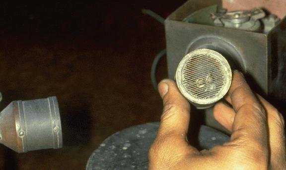
Figure 4.
4(a) One of Bose's transmitter antennas (being
held on the right of the picture). Note the polarizing grid; the spark gap is just
visible behind the grid. In the background behind this antenna part of the
high voltage equipment used to generate the spark can be seen. At the left of the picture is a receiving horn.
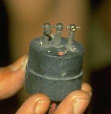
4(b) 4(b) A closeup of the spark gaps normally mounted inside the transmitting
antenna 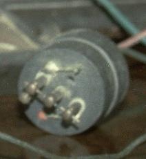 _
_ 
4(c)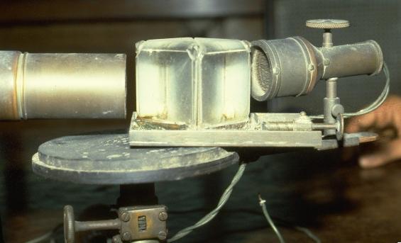
4(c) A complete setup showing the transmitting antenna at the left, with
the receiving antenna at right. Note the adjustment screw on top of the
receiving antenna, which is used to adjust the pressure of the point-contact
detector (see Fig. 5). In the center is a rotating table
(the "spectrometer circle" of Figure 2) on which various
microwave components (prisms, lenses, grids, polarizers etc.) may be mounted
for study. A dual-prism attenuator (see below) is shown in this photograph.
The arrangement as shown is not yet properly aligned.
Figure 4(a) is a photograph of one of his radiating antennas; part of the spark oscillations are generated
inside the overmoded circular waveguide. A polarizing grid is built into the antenna, clearly
visible at the radiating end of the waveguide.
Figure 4(b) shows a closeup of the dual spark gaps used for the transmitter; the sparks are generated between the 2 outer spheres and the inner sphere.
Figure 4(c) shows both a transmitting antenna (left) and the receiver (right),
with a dual prism in between set on the experimental rotating table.
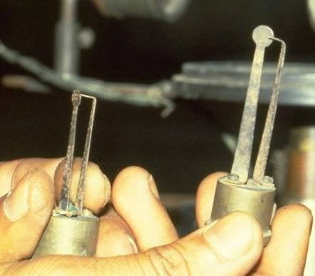
Figure 5. Two of Bose's point contact detectors, removed from the receiving antennas.
Figure 5 shows two of Bose's point contact detectors. In use, the detector would be placed inside
an overmoded waveguide receiving antenna, very much like the transmitting antenna shown in
Figure 4, and with a matching polarizing grid.
Bose measured the I-V characteristics of his junctions; an example characteristic curve of a
"Single Point Iron Receiver" is shown in Figure 6. The junction consisted of a sharp point of iron,
pressing against an iron surface, with pressure capable of fine adjustment. The different curves in
Figure 6 correspond to different contact pressures. Bose noted that the junction does not obey
Ohm's law, and that there is a knee in the curve at approximately 0.45 volts; the junction becomes
most effective at detection of short wavelength radiation when the corresponding bias voltage is
applied. He made further measurements on a variety of junctions made of different materials,
classifying the different materials into positive or negative classes of substance. In one experiment
he noted that increasing the applied voltage to the junction actually decreased the resulting
current, implying a negative dynamic resistance [15].
Figure 6. The I-V characteristics measured by Bose for a Single Point Iron Receiver. Note the
similarity to modern semiconductor junctions, with a knee voltage of about 0.4 volts.
Another of Bose's short-wavelength detectors is the spiral-spring receiver. A sketch of a receiver used for 5-mm radiation is shown in Figure 7; the spring pressure could be adjusted very finely in order to attain optimum sensitivity. The sensitive surface of the 5-mm receiver was 1 by 2 cm. The device has been described recently [3] as a "space-irradiated multi-contact semiconductor (using the natural oxide of the springs)." A surviving, somewhat larger, spiral spring receiver is shown in the photograph Figure 8. The springs are held in place by a sheet of glass, seen to be partly broken in this example.
Figure 7. Bose's diagram of his spiral-spring receiver used for 5-mm radiation.
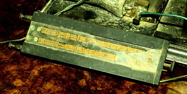
Figure 8. One of Bose's free-space radiation receivers, recently described [3] as a "space-irradiated multi-contact semiconductor (using the natural oxide of the springs)." The springs are kept in place in their tray by a sheet of glass, seen to be partly broken in this photograph.
Figure 9 is Bose's diagram of his polarization apparatus. The transmitter is the box at left, and a spiral spring receiver ('R') is visible on the right. One of the polarizers used by Bose was a cut-off metal plate grating, consisting of a book (Bradshaw's Railway Timetable, Figure 10) with sheets of tinfoil interleaved in the pages. Bose was able to demonstrate that even an ordinary book, without the tinfoil, is able to produce polarization of the transmitted beam. The pages act as parallel dielectric sheets separated by a small air gap.
Figure 9. Bose's diagram of his polarization apparatus. Note the spiral spring receiver 'R' to the
right.
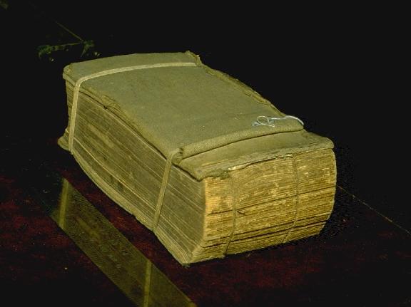
Figure 10. One of Bose's polarizers was a cut-off metal plate grating, consisting of a book
(Bradshaw's Railway Timetable) with sheets of tinfoil interleaved in the pages.
Bose experimented with samples of jute in polarizing experiments. In one experiment, he made a
twisted bundle of jute and showed that it could be used to rotate the plane of polarization. The
modern equivalent component may be a twisted dielectric waveguide. He further used this to
construct a macroscopic molecular model as an analogy to the rotation of polarization produced
by liquids like sugar solutions. Figure 11 shows Bose's diagram of the jute twisted-fiber
polarization rotator, and Figure 12 is a photograph of a surviving twisted-jute polarizer at the
Bose Institute.
Figure 11. Bose's diagram of twisted-Jute polarization elements, used to simulate
macroscopically the polarization effect of a certain sugar solutions.
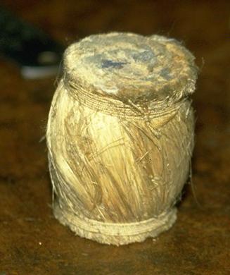
Figure 12. One of the twisted-jute polarizers used by Bose.
THE DOUBLE-PRISM ATTENUATOR
Bose's investigations included measurement of refractive index of a variety of substances. He
made dielectric lenses and prisms; examples are visible in Figures 1 and 2.
Figure 13. Bose's 1897 diagram of the double-prism attenuator.
One investigation involved measurement of total internal reflection inside a dielectric prism, and
the effect of a small air gap between two identical prisms. When the prisms are widely separated,
total internal reflection takes place and the incident radiation is reflected inside the dielectric.
When the 2 prisms touch, radiation propagates unhindered through both prisms. By introducing a
small air gap, the combination becomes a variable attenuator to incident radiation; this is
illustrated in Bose's original diagram, shown in Figure 13. Bose investigated this prism attenuator
experimentally; his results were published in the Proceedings of the Royal Society in November,
1897 [8]. Schaefer and Gross [16] made a theoretical study of the prism combination in 1910; the
device has since been described in standard texts.
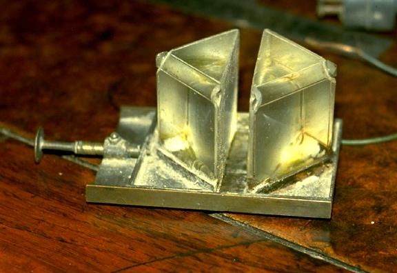
Figure 14. One of Bose's original double-prism attenuators, with adjustable air gap.
At the National Radio Astronomy Observatory in Tucson, Arizona a new multiple-feed receiver,
operating at a wavelength of 1.3 mm, has recently been built and installed on the 12 Meter
Telescope at Kitt Peak [17]. The system is an 8-feed receiver, where the local oscillator is
injected into the superconducting tunnel junction (SIS) mixers optically. With an SIS mixer receiver the power level of the injected
local oscillator is critical; each of the 8 mixers requires independent local oscillator power
adjustment. This is achieved by adjustable prism attenuators. Figure 15 shows 4 of these 8 prism
attenuators, installed on one side of the 8-feed system; this can be compared with Figure 14,
which is a photograph taken at the Bose Institute in Calcutta in 1985, of an original prism system
built by Bose.
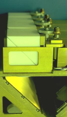
Figure 15. Four of the 8 double-prism attenuators used to control local oscillator injection into the NRAO 1.3-mm 8-beam receiver in use at the 12 Meter Telescope at Kitt Peak.
CONCLUSIONS
Research into the generation and detection of millimeter waves, and the properties of substances
at these wavelengths, was being undertaken in some detail one hundred years ago, by J.C. Bose in
Calcutta. Many of the microwave components familiar today - waveguide, horn antennas,
polarizers, dielectric lenses and prisms, and even semiconductor detectors of electromagnetic
radiation - were invented and used in the last decade of the nineteenth century. At about the end
of the nineteenth century, many of the workers in this area simply became interested in other
topics. Attention of the wireless experimenters of the time became focused on much longer
wavelengths which eventually, with the help of the then unknown ionosphere, were able to
support signalling at very much greater distances.
Although it appears that Bose's demonstration of remote wireless signalling has priority over
Marconi, he was the first to use a semiconductor junction to detect radio waves, and he invented
various now commonplace microwave components, outside of India he is rarely given the
deserved recognition. Further work at millimeter wavelengths was almost nonexistent for nearly
50 years. J.C. Bose was at least this much ahead of his time.
ACKNOWLEDGEMENTS
I wish to thank the Bose Institute in Calcutta for help with material, and for permission in 1985 to
photograph some of the original equipment of J.C. Bose, including the photographs shown from
Figures 4 to 14 in this article. I thank Mrs. Nancy Clarke for help in preparing the manuscript.
REFERENCES
[1] H. Hertz, Electric Waves. London: Macmillan and Co. Ltd., 1893. (Reprinted by Dover.)
[2] John F. Ramsay, "Microwave Antenna and Waveguide Techniques before 1900," Proc. IRE., Vol.46, No.2, pp. 405-415, February 1958.
[3] K.L. Smith, "Victorian Microwaves," Wireless World, pp. 93-95, September 1979.
[4] Lord Rayleigh, "On the passage of electric waves through tubes, or the vibrations of dielectric cylinders," Phil. Mag., vol.43, pp.125-132, February 1897.
[5] Oliver Lodge, Signalling Across Space Without Wires. Fleet Street, London, U.K.: "The Electrician" Printing & Publishing Company, 1908, 4th Ed., p. 83. (First edition published in 1894 under the title, The Work of Hertz and His Successors.)
[6] A. Righi, L'Ottica delle Oscillazioni Elettriche. Bologna, Italy: N. Zanichelli, 1897.
[7] J.C. Bose, "On the determination of the wavelength of electric radiation by a diffraction grating," Proc. Roy. Soc., vol. 60, pp.167-178, 1897.
[8] J.C. Bose, Collected Physical Papers. New York, N.Y.: Longmans, Green and Co., 1927.
[9] P. Lebedew, "Ueber die Dopplbrechung der Strahlen electrischer Kraft," Annalen der Physik und Chemie, series 3, vol.56, no.9, pp.1-17, 1895.
[10] Monoranjon Gupta, Jagadis Chandra Bose, A Biography. Bombay, India: Bhavan's Book University, 1952.
[11] Bimalendu Mitra, Sir Jagadis Chandra Bose: A Biography for Students. Hyderabad-Bombay-Calcutta, India: Orient Longman,Ltd., 1982.
[12] B. Mitra, "Early Microwave Engineering: J. C. Bose's Physical Researches during 1895-1900," Science and Culture, vol.50, pp.147-154, 1984.
[13] Photograph from Acharya Jagadis Chandra Bose, Birth Centenary, 1858-1958. Calcutta: published by the Birth Centenary Committee, printed by P.C. Ray, November 1958.
[14] G.L. Pearson, and W.H. Brattain, "History of Semiconductor Research," Proc. IRE, 43, pp.1794-1806, 1955.
[15] J.C. Bose, "On the Change of Conductivity of Metallic Particles under Cyclic Electromotive Variation," originally presented to the British Association at Glasgow, September 1901, reproduced in Collected Physical Papers, J.C. Bose, Ed. New York, N.Y.: Longmans, Green and Co., 1927.
[16] C. Schaefer and G. Gross, "Untersuchungen ueber die Totalreflexion," Annalen der Physik, vol 32, p.648, 1910.
[17] J.M. Payne & P.R. Jewell, "The Upgrade of the NRAO 8-beam Receiver," in Multi-feed Systems for Radio Telescopes, D.T. Emerson & J.M. Payne, Eds. San Francisco: ASP Conference Series, 1995, vol. 75, p.144.