by Darrel Emerson.
Antenna Compendium Vol 5, published  by ARRL (1996), pp.87-95.
(Copyright on original article is held by the ARRL)
This article looks at the maximum theoretically possible directive gain that could be obtained with an endfire array of given length or number of elements, and compares this with practical results in the literature. Various antenna design principles are explained, including ordinary endfire, the Hansen-Woodyard array, the surface wave antenna and supergain arrays. The theoretical concepts are compared with practical antennas, including phased arrays, Yagis and helical antennas, and laboratory-tested superconducting arrays.
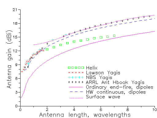
The above diagram compares the gains predicted by theoretical designs for an endfire array - the ordinary endfire, the Hansen-Woodyard and surface wave arrays - with the performance of some practical antennas from the literature. The modern generation of Yagi antennas are in very close agreement with the surface wave theory, and also in good agreement with gains derived from the Hansen-Woodyard design principle published in 1938. Note the relatively poor performance of the helix, although all theoretical and practical designs are somewhat better than the ordinary endfire.
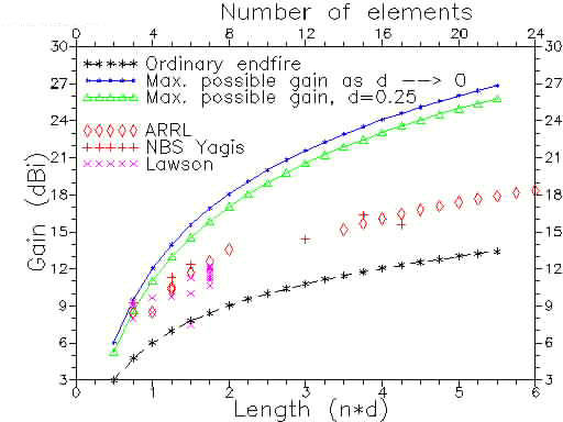
The figure above compares the gains actually obtained with ordinary endfire arrays, and Yagi antennas from the literature, with the potential gain of supergain arrays. With a supergain array, higher gain is in fact obtained with the elements closer together, but then the antenna Q rises so rapidly that the configuration rapidly becomes impossible to realize.
The power gain of an ordinary endfire array increases directly as N, the number of elements. The maximmum THEORETICAL power gain of a supergain array increases as N squared. This theoretical limit of N squared is reached as the element spacing tends to zero. However, with quarter-wavelength element spacings, the green curve above shows that the full theoretical N-squared gain (upper blue curve) is very nearly reached. But even with the quarter-wavelength spacing, this degree of supergain is still impossible to achieve in practice.
With antenna lengths up to nearly a wavelength, some practical Yagi antennas operate well into the supergain region. (Note in the above figure that the practical Yagi gains are for arrays of dipoles, while the ordinary endfire and the supergain curves are for arrays of isotropic elements. This biases the gains of the real antennas a little high) However, for antennas of more than just a few elements, the supergain principle leads to impossibly high Q values; the potential antenna gains are unlikely ever to be realized in practice.
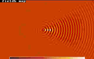
Ordinary endfire, field snapshot
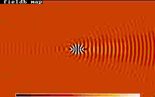
Max. supergain endfire, field snapshot
The upper of the 2 images above gives a snapshot of the field distribution around an "ordinary" endfire 13-element array. The element spacings are one quarter wavelength, giving a total antenna length of 3 wavelengths. Each element is fed with equal current, progressively phased by 90 degrees. (For simplicity the individual elements were assumed to behave as isotropic radiators rather than dipoles, but this has very little effect on the end result.) The radiation is clearly concentrated in one direction, to the right, with more or less spherical wavefronts spreading out from the centre of the antenna. The gain of this antenna is 11.14 dBi.
The lower of the 2 images above gives a field snapshot of the same 13-element antenna, fed with the same transmitter power, but with the relative current amplitude and phase in each element arranged to give the maximum theoretical directive gain. It can be shown theoretically that NO OTHER DISTRIBUTION OF CURRENT AND PHASE CAN EVER GIVE HIGHER DIRECTIVE GAIN for this 13-element array. The gain is 21.24 dBi, more than 10 dB higher than the "normal" endfire array above.
Although the application of supergain to this 13-element array has given an extra 10 dB of gain, and in theory the antenna would work, in practice it could never be built, even if superconducting elements were used to eliminate loss. The antenna Q would be about 100 million, implying for example impossible construction tolerances and impractically high precision in feeding the individual elements with currents of the correct relative amplitudes and phases. Even if it could be built and energized, it would show a bandwidth of little more than 1 Hz on the amateur 2-m band.
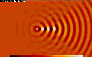
Ordinary endfire, closeup field snapshot
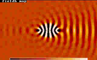
Supergain, closeup field snapshot
The 2 coloured images above zoom in on the fields closer to the 13-element antennas described above. Note that, although for the ordinary endfire array the fields decay gradually from the centre of the antenna, for the supergain antenna (lower image) there is a fairly extensive region of intense field surrounding the antenna. The extent of this high field region is about the same as the physical extent of a normal (non-supergain) antenna giving the same gain. So although the supergain is physically smaller, nevertheless a clear space must be left around the antenna so that nothing intrudes into the extreme high-field region to disturb the operation of the antenna. In other words, supergain antennas don't save space.
Finally, note that the field expanding to the right from the ordinary endfire array does so more or less as spherical wavefronts. For the supergain antenna however, the field is much more focused, and the wavefronts start out nearly parallel - hence diverging much less, giving the high directive gain.
For more detail, and for literature references, please refer to the full article (soon to be) published in the ARRL's Antenna Compendium Volume 5.