by Dr. D.T. Emerson, National Radio Astronomy Observatory (NRAO++).
Antenna Compendium Volume 4, pp 64-68, 1995, published by the ARRL.
(Copyright on original article is held by the ARRL)
The axial-mode helix antenna, first described by Kraus in 1947, is probably the most widely used circularly-polarized antenna, either in space or on the ground. There are conflicting claims for the gain of the antenna; most amateur literature, and even many standard textbooks, quote gains which are far too optimistic. More realistic gain relationships are available now in the professional antenna journals, but are not well known in amateur circles.
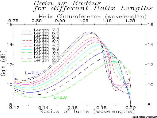
This article summarizes probably the most extensive numerical modelling calculations on the helical antenna ever performed. NEC-2 was used to model some 10,000 different helical antennas, systematically changing the physical parameters of the antenna and investigating the effect on gain and feed match. For each calculation, between 600 and 1400 segments were used to model an antenna; with frequent checks on the validity of the calculations. Some 3000 hours of networked Sparc workstation compute cycles were used for the study.
The modelling data were compared with results from the professional antenna literature. Reassuringly, the modelling gives results which are intermediate between published experimental and theoretical work. The maximum possible gains are up to 4 or 5 dB lower than those derived from the original Kraus formula for gain. The maximum gain increases much more slowly with increasing antenna length than the simple Kraus formula would predict.
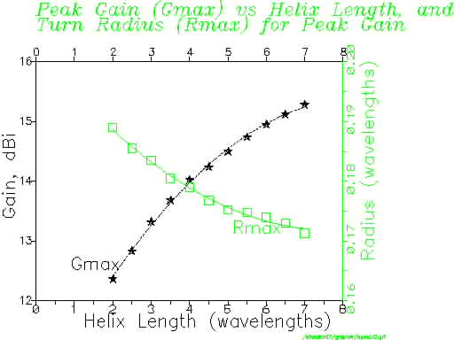
An empirical expression for the maximum possible gain Gmax of the helical antenna as a function of its length L in wavelengths is:
Gmax(dB) = 10.25 + 1.22 L - 0.0726 L^2
This expression is only valid for lengths L between 2 and 7 wavelengths.
An empirical expression for the turn radius Rmax at which peak gain occurs as a function of length L in wavelengths is:
Rmax = 0.2025 - 0.0079 L + 0.000515 L^2
Again, this is only valid for lengths between 2 and 7 wavelengths.
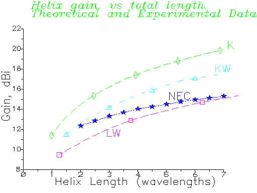
In summary, this extensive modelling study is in good agreement with theory and measurement from the professional literature, all of which show that the simple Kraus formula for gain of a helix is far too optimistic - by up to 4 or 5 dB.
The modelling shows that, at a given value of turn spacing, the optimum turn radius for peak gain decreases slightly as the helix is made longer. The gain is almost independent of wire diameter, or of the presence of a short feed stub between the ground plane and the start of the helix. The resistance of wire used to construct the helix, even if several times worse than aluminium, has little effect on efficiency. A half-lambda square groundplane is nearly as good as an infinite groundplane. The use of radials, rather than a continuous groundplane, gives a gain penalty of some 3.5 dB.
Please consult the original article for more results, and for literature references. A preprint of a more detailed article on the gain of the helix antenna, prepared for the professional literature, is available from the author. (Please send e-mail to demerson@nrao.edu.)
++ The National Radio Astronomy Observatory is a facility of the National Science Foundation, operated under cooperative agreement by Associated Universities, Inc.