This is a summary of material which appeared in The AMSAT Journal, Volume 20, No. 1, Jan/Feb 1997. pp.1,4-11.
(Last revised February 7th 1997)
The Mars Global Surveyor (MGS) was launched towards Mars on November 7 1996, and is expected to reach its destination in September 1997. When it arrives, a relay transmitter (the Mars Relay or MR) will remain in orbit around the planet, eventually to be relaying information from sensors on the planet's surface back to earth. This relay transmits to the probes on the Martian surface on 437.1 MHz.
Starting on November 25 1996, when the MGS was 5 million km from the Earth, the MR 437 MHz transmitter was tested, putting 1.3 W into a near-isotropic antenna. Radio amateurs were invited to try to detect the carrier of this transmission during the several hours when it was active. Several hundred radio amateurs took part in the test, which was coordinated over the Internet. Below are shown some of the results from AA7FV during this test. The antenna (a single 15 element Yagi) was probably one of the smallest used anywhere to receive the signal, but relatively high signal-to-noise ratio was achieved by narrowing down the bandwidth to just over 0.01 Hz. This required some special techniques, which are outlined, with some of the results, below.
These links explain the background and give more details of the Mars Relay test.
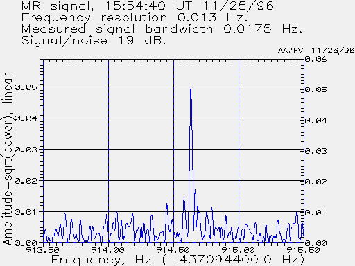
The following spectrum was observed on 11/25/96 at 15:54:40 UT, when the MGS Relay transmitter was transmitting 1.3 W, into a nearly isotropic antenna, at a distance from the Earth of 5 million km. 105 seconds of data have been used to generate a true DSP filter frequency resolution of 0.0131 Hz. The measured signal bandwidth is 0.0175 Hz. In the analysis, an injected stable tone, loosely coupled to the antenna during the measurements, was used to determine and compensate for receiver phase and frequency drift. Note that the total range of the spectrum shown below is only 2 Hz.

The vertical scale is linear in amplitude, not power, and is in arbitrary units. The s/n on the peak signal, compared to the mean power >0.5 Hz away from the signal, is approximately 19 dB. In the analysis an assumed frequency drift rate of -0.02 Hz/s was used, rather than the predicted -0.03649 Hz/s from Doppler changes. This compensates for a slight but steady frequency drift at the MR transmitter.
Summary:
Location: AA7FV in Tucson, AZ, 110.916 W, 32.3302 N.
Antenna: single 15x15 element crossed Yagi, RHCP,
         gain ~16.5 dBic.
Antenna preamp, NF 0.4 dB.
Receiver:  R7100, with phase referencing to a highly stable
         tone,   loosely coupled to the antenna, at 437095000 Hz.
Measured signal frequency at 15:54:40 UT:       437095314.6 +/-5 Hz.
Predicted signal frequency at 15:54:40 UT at AA7FV: 437095326 Hz.
Receiver DSP bandwidth (-3 dB) 0.0131 Hz
Measured signal width:    0.0175 Hz.
Assumed Doppler+drift rate: -0.02 Hz/s (instead of -0.03649 Hz/s)
Measured signal/noise:  19 dB
The following plot shows the measured frequency of the MR between 14;00 UTC and 21:00 UTC on November 25 1996. The solid curve is the predicted frequency at AA7FV, taking into account the geocentric velocity and acceleration of the MGS, and the Earth's rotation. Most of the change in frequency comes from the rotation of the Earth.
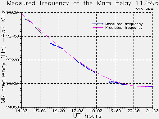
The measured frequencies follow the predicted quite nicely, although there are occasional deviations of up to 40 Hz. It is believed these instabilities are in the MR transmitter itself, perhaps coming from a temperature change either as the spacecraft rotates in sunlight, or perhaps from heat from transmitters being turned on. A 40Hz shift corresponds to about 6 degrees C change in MR temperature. The frequency standard at AA7FV is believed to be accurate to within +/-5 Hz, and any changes in frequency of this standard during the 7-hour measurement period are expected to be much less than +/-1 Hz. The slightly anomalous rate-of-change of frequency, resulting from MR transmitter drift, is obvious in the plot around 16:00 UT. It is also seen in the Stanford data (see the link below to Stanford measurements and MR power and frequency.)
The following plot shows the amplitude measured on the MR signal at AA7FV. Before about 15:30 UT very few measurements were made. The amplitudes between about 15:30 and 16:10 agree particularly well with the data from the Stanford 150-ft dish. From 16:18 to 17:40 the spacecraft was being manoeuvered, resulting in large changes in signal in the direction of the Earth.
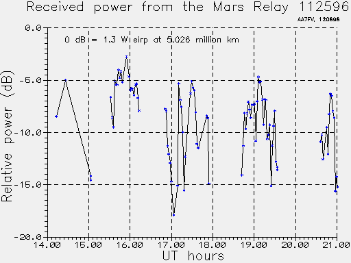
The 0 dB reference on the above plot is the level predicted for a 1.3 watt transmitter and isotropic antenna at a distance of 5.025 million km, corresponding to the MGS at the time of the measurements. The broad peaks in signal occurring every 100 minutes correspond to the rotation of the spacecraft, as its antenna rotates towards the earth. From 16:18 UT until 17:40 UT the spacecraft began instrument calibrations, with the its on-board camera being swept first past the Earth and then the Moon. The MR disappeared below the local horizon at 21:00 UT.
The following plot shows the amplitude of the MR signal between about 15:30 UT and 16:30 UT measured with the Stanford 150-ft dish, and by the AA7FV 15-element Yagi. The origin of each dB scale is arbitrary. The Stanford data are extracted (with permission) from the web plot available on http://www-star.stanford.edu/projects/relay/mr-cw.html (see the link below.).
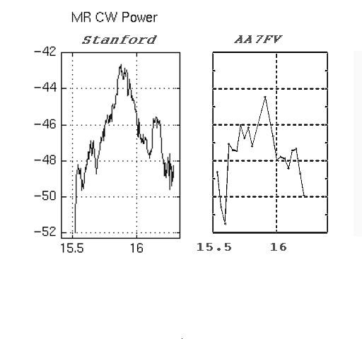
For a full comparison with these AA7FV measurements, see the data measured with the 150-ft dish at Stanford.
In preparation for the MGS Mars Relay tests, many tests were made of the frequency stability of the standard reference signal used at AA7FV. Over a period of many days, the frequency difference between the local standard and the transmissions from GOES8 and GOES9 was measured. These satellites are in a geostationary orbit, and send telemetry with time information modulated on carriers at 468.8375 and 468.825 MHz. See the www link below for more details of these transmissions.
For the frequency stability tests, the AA7FV frequency synthesizer (the HP5100/5110 combination) was put 300 Hz below the nominal GOES-9 transmisison on 468.825 MHz. The difference in frequency was recorded automatically, almost continuously, for several days.
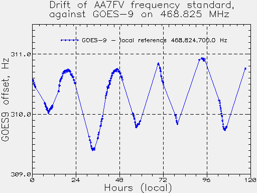
The above plot shows the difference in frequency between the transmission from GOES9, nominally on 468.825 MHz, and the local frequency synthesizer set 300 Hz below this nominal frequency. The absolute accuracy of the local frequency synthesizer is believed to be within +/- 5 Hz, so the transmitted signal from GOES9 may be about 10 +/-5 Hz high in frequency. Data are shown here for 5 days. The peak-to-peak deviation in difference frequency in that time was a little over +/-0.5 Hz. The obvious daily variation in frequency is mainly a result of the orbital motion of the satellite, but probably also in part due to the changing ambient temperature of the room containing my local frequency standard.
Similar measurements were made using GOES8 as the reference, on 468.8375 MHz. The average frequency from GOES8 was found to be within 1 Hz of its nominal value, based on the AA7FV standard. The results from GOES8 were very similar to the above, with a near-sinusoidal variation in frequency similar to that of GOES9. Unless BOTH GOES8 and GOES9 display frequency variations drifting in the same way as the AA7FV standard, then the conclusion is that AA7FV frequency stability is within +/-0.7 Hz over any 24-hour period. The maximum rate of change of frequency is about 1 Hz in 10 hours, or 0.000028 Hz/second. A measurement of the Allan variance, using 100-second integration periods, on the difference frequency between AA7FV and GOES9 gave a value of 1.4E-11.
The GOES Satellite Time Service is transmitted by GOES-8 and GOES-9 on 468.8375 and 468.825 MHz. The carrier of the transmission is extremely stable, and any changes in Doppler shift caused by orbital motion are very small. These transmissions make a very convenient high quality stable frequency reference.
The figure below shows the hardware arrangement, with a locally generated stable signal from the HP5110/HP5100 frequency standard and frequency synthesizer loosely coupled to the antenna.
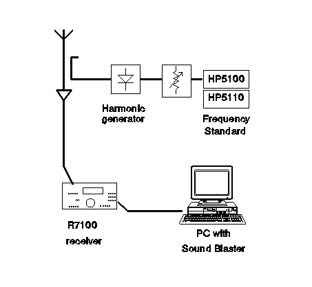
The high sensitivity was achieved by narrowing the bandwidth to 0.013 Hz. This receiver drifts many Hz in the ~100 seconds of data acquisition needed to obtain 0.01 Hz resolution. The high resolution was made possible by phase-referencing. A locally generated stable frequency was injected into the receiver passband. The phase and frequency of this reference signal was measured 10 times a second, giving a measure of the overall receiver instability and phase noise. The measured phase and frequency offset was then subtracted from the entire spectrum derived from each 0.1 seconds of data, and the corrected spectrum was then recomputed back into the time domain, overwriting the raw data.
The 105 seconds of corrected data were then used to compute a spectrum with 0.013 Hz resolution. Because phase and frequency drifts have been measured and corrected, phase coherence is now maintained over the entire 105-second period, allowing a true frequency resolution of 0.013 Hz. (Computationally this procedure is very inefficient; the same result could have been obtained without having to compute the inverse FFTs of each 0.1 second subset of data. However, the approach described here is conceptually very straightforward and was relatively easy to implement and debug.)
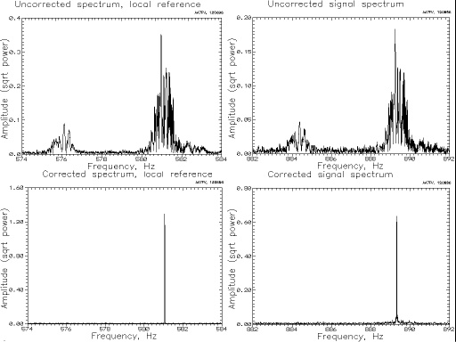
The above plots illustrate phase referencing on a test signal - the telemetry carrier transmitted from the geostationary satellite GOES-9 on 468.825 MHz. The reference signal was ~300 Hz lower in frequency than the GOES-9 signal. In the receiver, the reference signal appeared at about 580 Hz, and the GOES-9 signal at about 890 Hz. Each spectrum shows a total frequency range of 10 Hz.
The upper 2 plots show the UNCORRECTED spectrum on the reference signal (left) and the GOES-9 signal (right). The energy from both signals is spread over several Hz. The secondary peak a few Hz lower in frequency implies that the receiver jumped about 5 Hz in frequency during the 105-second data acquisition period. Note that the shapes of the spectra, on the reference signal and on GOES-9, are almost identical.
The lower 2 spectra are from the same data, but after applying the phase reference correction. The phase and frequency drifts have been removed completely both on the local reference (used to measure the frequency and phase drifts) but also on the GOES-9 signal. The measured line width of the GOES-9 signal is now only 0.013 Hz, the theoretical value.
The following files contain the raw data from which the above Mars Relay spectrum was generated. The original data are in a .VOC format, with 105 seconds of data sampled at 5 kHz. A steady tone at about 500 Hz is easily audible in the recording, corresponding to the stable reference signal injected into the receiver passband at 437,095,000 Hz. The signal from the Mars Relay probe starts at approximately 314.6 Hz above this strong steady tone, but the offset changes owing to changing Doppler drift caused by the probe's heliocentric orbital motion and slight drift of the transmitted signal . Both reference tone and probe signal have additional, but identical, drifts caused by receiver instabilities.
The original .VOC data file is available below, compressed with PKZIP. The data have also been converted to .WAV format, similarly compressed.