John Payne
Graham Moorey
Last changed 1999-May-2
Revision History:
1998-11-18:
Major revision
1999-05-02:
Minor specification changes in Table 5.1, revised deadlines in Table 5.2.
Section 5.1.7 on Cryogenics added, and Evaluation Receiver General
section 5.1.8 added.
Summary
The receiver development plan consists of two distinct efforts. One will result in a receiver suitable for the evaluation of the first antenna. A copy of this receiver will be constructed at the end of the D&D phase permitting the first interferometry tests to proceed on delivery of the second antenna. These receivers are designed to be "throw-away" items, although many of the components and techniques developed will be used in the final receivers for the MMA. These initial receivers are referred to as "evaluation receivers" in this Chapter. The specifications for these receivers are given in Table 5.1 and the principal milestones in Table 5.2.
The second effort will be to develop plans and some prototype components for the final receivers
that will enable the construction of the receivers to proceed in a timely manner at the end of the
D&D phase. Here these receivers are referred to as the "production receivers."
| Frequency Band | Detector Element |
| 30-40 (33-45?) GHz | HFET amplifier |
| 86-115 GHz | SIS mixer |
| 85-105 GHz
(HFET amp covers 75-105 GHz) |
HFET amplifier |
| 210-270 GHz | SIS mixer |
| All bands are dual linear polarization. | |
| Task | Date |
| Optics decision | Pending |
| 4k refrigerator selection | January 1999 |
| Dewar design complete | September 1999 |
| All components delivered | End 1999 |
| Receiver assembly complete | May 2000 |
| Receiver tests complete | July 2000 |
| Deliver receiver to VLA site | June 2001 |
5.1 Evaluation Receivers
5.1.1 Introduction
The receivers designed for the evaluation of the first antenna and the initial interferometer
tests will be independent of the receivers that will finally be mass-produced for the MMA. Some
components will be similar or identical and efforts will be made to design the receivers in such a
way that some parts of the design will be transferable to the production receivers. However the
focus of the effort will be to produce in a timely manner a receiver system that is suitable for the
initial tests. This will involve the use of many components identical to those used on the present
12m receivers.
5.1.2 Specifications
The evaluation receivers will be equipped with three
frequency bands. These are 30-40 GHz (HFET: possibly soon to be revised to
33-45 GHz), 86-115 GHz (SIS), 85-105 GHz (HFET) and 210-270
GHz. The I.F. will be 4-6 GHz for the 1 mm and 3 mm SIS receivers,
but possibly 4-12 GHz for the HFET systems. All receivers will be dual
channel receiving orthogonal linear polarizations. The noise
performance of the receivers will be the best that can be
obtained with today's components and will be more than adequate
for the initial measurements. An important point is that
continuum measurements will be needed to measure aperture
efficiency at the various frequencies. Beam switching with the
nutating sub-reflector will be used and, due to the mechanical
nature of the switching mechanism, it is necessary for the
detected output of the receivers to have a power spectrum that
is flat down to a few Hz. There seems to be some doubt that the
high frequency HFET amplifiers will satisfy this requirement and
this is discussed in more detail below.
5.1.3 The Receiver Dewar
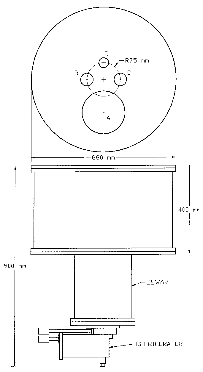
The layout of the dewar will follow that shown in Figure 1,
which may be regarded as a baseline design. This layout follows
the ideas that are used in the present Tucson receivers with the
exception that the change in frequency bands is achieved by
simply changing the pointing of the antenna rather than rotating
external optics. This system results in errors due to off-axis
operation (see
MMA Memo 175 ), but these errors, coma, etc., are shown to
be negligible.

5.1.4 The Receiver Optics
For the evaluation receiver, we plan a simple optical
arrangement with "clean" optics that follow the suggestions in
MMA Memo #215 .
5.1.5 Polarization Diplexing
In the past, the NRAO receivers have used room temperature
wire grid polarization diplexers. Recently, a full waveguide
band diplexer (ortho mode transducer, OMT) has been developed
for the 3 mm band and it is hoped to extend this technique to
the 1 mm band. This will result in lower receiver noise as the
OMT will operate at cryogenic temperatures.
5.1.6 Evaluation Receiver Block Diagrams
5.1.6.1 Introduction
The block diagrams for the different receiver bands described here are tentative and may be
modified extensively in the next few months.
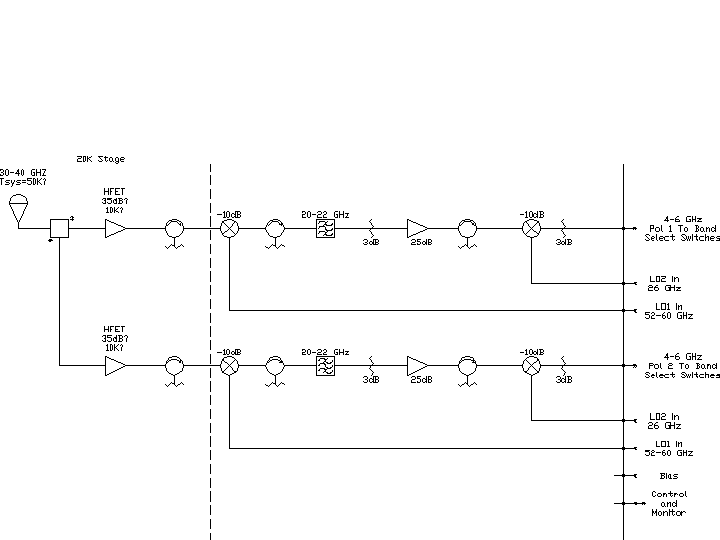
5.1.6.2 The 30-40 GHz Receiver
The block diagram for this receiver is shown in Figure 2.
5.1.6.3 The 86-115 GHz Receiver
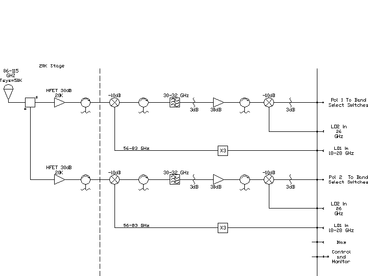
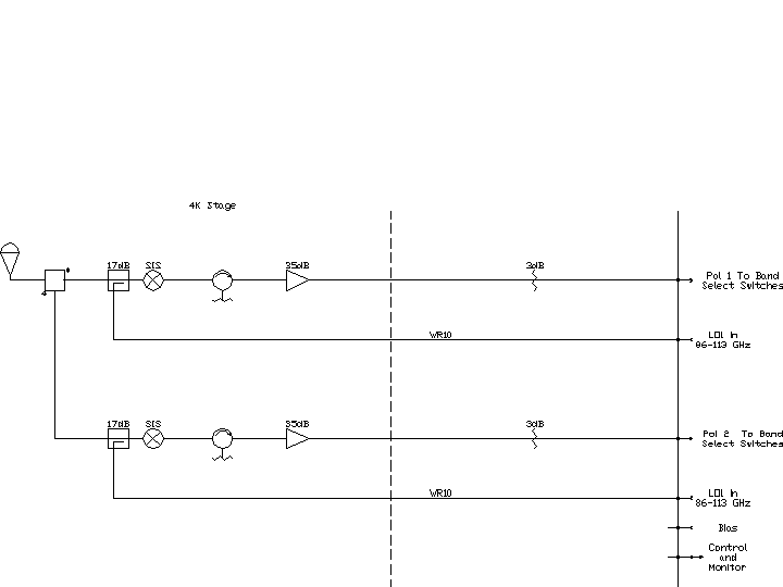
There is uncertainty at present about the performance of the HFET amplifiers for use at this
frequency. What is proposed here is that the evaluation receivers contain two receivers in this
band : one , a dual polarization receiver using HFET amplifiers, the other a similar receiver using
SIS mixers. In this way we hope to make an evaluation of the low frequency post detection noise
that will be critical for continuum observations using the nutating sub-reflector. Although it
should be possible to evaluate the receiver performance in the laboratory prior to telescope
observations it is felt that telescope observations will give the most unambiguous results. Block
diagrams of both these receivers is shown in Figures 3 and 4. The SIS receiver will use the
tuneable mixers that are in use at the 12m telescope today.
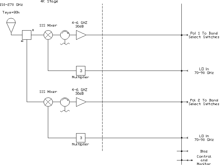
5.1.6.4 The 210-270 GHz Receiver
A block diagram of this receiver is shown in Figure 5. The components are all today's
technology, although it is anticipated that a major effort will go into achieving phase stability.
Again, the mixers used will be identical to the fixed backshort design used on the 12m telescope
today.
5.1.7 Evaluation Receiver Cryogenics
A decision has been made to power all electronics and helium compressors
from 380 Volt, 3 phase 50 Hz, or 220 Volt single-phase 50 Hz; this corresponds
to the standard Chilean power grid. As a result of the 50 Hz mains frequency
the rotational speed of the compressor motors will drop by ~17%, lowering
the helium flow rate proportionally. To provide sufficient helium flow
to the GM refrigerator a new prototype compressor system will be developed
using two Scroll compressors in parallel for the GM section, and a
single Scroll for the JT circuit.
5.1.8 Evaluation Receiver, General Points
The evaluation receivers will be equipped with an integral power supply
system. Local control and monitoring will be provided through a
Receiver front panel and remote control and monitoring via a simple
I/O interface bus. The initial LO sources will be tunable phase-locked
Gunn oscillators with a multiplier for the 1 mm band. An IF output
level of -60 dBm/MHz will be provided for each polarization.